Wednesday, February 28, 2024

Create CAE Simulation Material Data Using Scripts

 For users conducting CAE analysis, material definition can be complex process. It is meticulous because the crucial material parameters require confirmation of their accuracy for each parameter. Furthermore, material definition can be laborious when dealing with numerous materials and diverse properties, as defining and editing attributes becomes a substantial task. An efficient method to define materials is to use scripts. The large-scale general simulation CAE software WELSIM supports script-defined materials through an automated testing system, facilitating the definition of a considerable material dataset using XML scripts.

This article uses examples to demonstrate the method of script-based creation of a large dataset of materials in WELSIM.

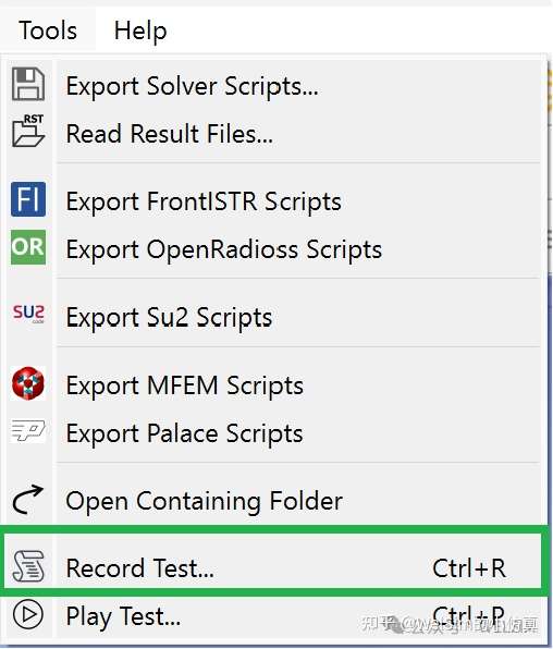
  1. Build a single material data through GUI. (If familiar with XML syntax, you can also refer to existing XML test files and write your own). Then, click Record Test.

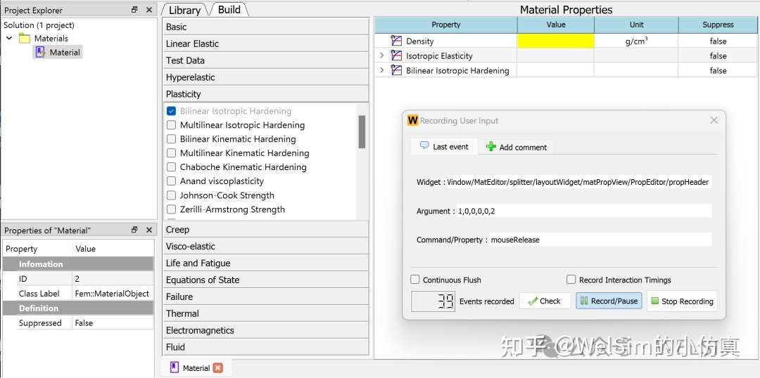
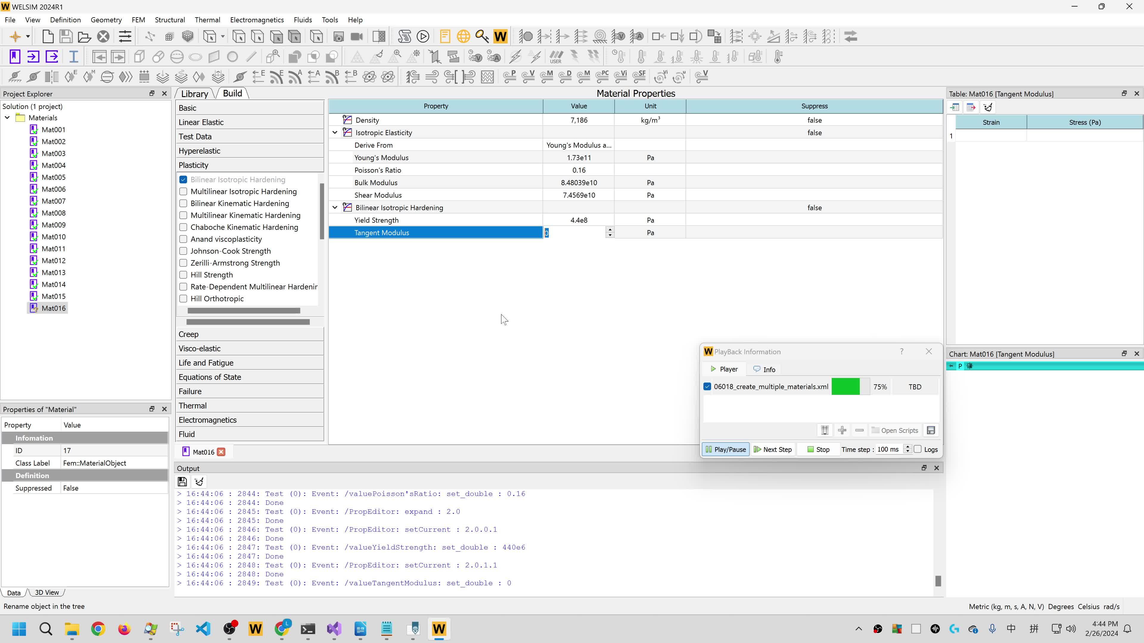
Create a new material object, naming it Mat001. Next, open the material editing panel and sequentially add density, isotropic elasticity, and bilinear isotropic hardening properties. These properties are commonly used in elastic-plastic models.

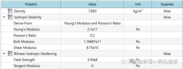
Input the relevant parameters. After completing the editing operations, the material properties should appear as follows:

2. Test a single material data file.

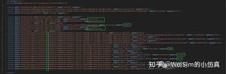
Click the stop recording button, and the macro command for graphical operations is recorded which generates the script. Open the recorded XML file with a text editor, make slight modifications, delete redundant lines, and obtain the script for a single material. In the figure below, the green-boxed part indicates the modifications for other materials, expanding to derive additional materials. These include the material object’s position in the project tree window, material name, material object ID, and material property parameters.

3. Copy and paste a single material, making the necessary modifications.

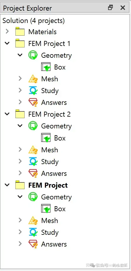
Copy and paste the text from the figure, modifying the green-boxed parts to create a new material. This article creates a total of 21 materials. The parameters for material properties, all using bilinear isotropic hardening plasticity, are listed in the table below.

4. Complete the script, run, and debug.

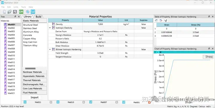
With the script editing completed, it can be run and tested. After running it, proceed directly to the subsequent simulation analysis tasks. Alternatively, material data can be exported for use in other software. The materials exported from WELSIM can be opened in MatEditor, as shown in the figure below.

Video demonstration during script execution is provided.

Conclusion

The script file used in this example is open-source and saved in the WELSIM public test library under the filename ”06018_create_multiple_materials.xml”. This example creates a total of 21 material datasets, each with similar properties but various numerical values. Furthermore, different material properties can be added in the script, supporting a more diverse material dataset.

Using scripts to effectively establish material datasets saves editing time, reduces errors, and is easy to maintain. Scripts can be easily modified for use in other material datasets, which displays strong adaptability. It is the ideal method for creating and maintaining large material datasets.

The script language for material definition may vary depending on the CAE software. In this example, XML is used. Other CAE software may use different languages, such as Python or JavaScript.

WELSIM is the #1 engineering simulation software for the open-source community.

Tuesday, February 27, 2024

使用脚本批量定义CAE仿真材料数据

 对于使用CAE进行仿真计算的的用户而言,材料的定义是一个细致且繁琐的过程,细致是因为材料参数对于仿真结果至关重要,需要确认每个参数的准确性;繁琐是当材料较多且含有多种属性时,定义和编辑属性的工作量较大。而采用脚本来定义材料是一个很好的方式。大型通用仿真CAE软件WELSIM可以通过自动化测试系统支持脚本定义材料,对于大量的材料集,可以通过XML脚本实现。

本文使用实例,演示在WELSIM下使用脚本建立大量材料数据的方法。

1. 通过GUI建立单个材料数据。(如果对XML语法熟悉,可以参考已有的XML测试文件,自行编写)。打开自动化测试的录制功能。

新建一个材料节点,设置节点名称为Mat001。打开材料编辑面板,按照步骤先后加入密度,各向同性弹性,双线性的各向同性硬化属性。这是弹塑性模型常用的材料属性。

输入相关参数。编辑操作完成后的材料属性显示如下:

2. 测试单个材料数据文件。

点击停止录制按钮,图形化操作宏命令录制完毕,脚本自动生成。使用文本编辑器打开录制好的XML文件,稍作修改,删除冗余的部分,即可得到单个材料的脚本。如下图所示,绿色方框部分是其他材料的修改部分,用于拓展得到其他材料。分别是材料节点在项目树窗口中的位置,材料名称,材料节点ID,和材料属性参数。

3. 复制粘贴单个材料,并做相应修改。

将上图中的文本进行复制粘贴,并修改绿色方框部分,即可得到一个新的材料。本文一共创建21个材料。材料属性的参数如下表所示,均采用双线性各项同性硬化塑性。

NameDensity(kg/m3)Young’s Modulus (GPa)Poisson's RatioYield Stress (MPa)
Mat0178502100.2355
Mat0263612930.19375
Mat0357511520.13461
Mat0458551740.1355
Mat0563771650.11555
Mat0655042330.11276
Mat0757601670.16460
Mat0861541990.1283
Mat0953602750.3591
Mat1073401820.14509
Mat1163872480.28502
Mat1259392140.2438
Mat1374361700.27509
Mat1479072210.28502
Mat1560371530.16438
Mat1671861730.23509
Mat1759312110.27422
Mat1877462190.17414
Mat1956742870.17415
Mat2070882070.11428
Mat2157191530.11498


4. 完成脚本,运行并调试。

至此脚本编辑已经完成,可以运行并测试。运行完成后,可以直接进行接下来的仿真分析工作。也可以导出材料数据,在其他软件中打开。如下图所示WELSIM中导出的材料在MatEditor中打开。


脚本运行时的视频演示如下。

00:36

总结

本例使用的脚本文件已经开源,并保存在WelSim的公共测试库中,文件名称为06018_create_multiple_materials.xml。本例共创建21个材料数据集,每个材料的属性相似,只是具体数值不同。此外,也可以在脚本中添加不同的材料属性,支持更加多样性的材料集。

使用脚本创立材料集,可以有效的节约编辑时间,不易出错,同时易于维护,已经编辑好的脚本稍作修改即可用于其他材料集,可拓展性强。是快速建立和维护大量材料集的理想方式。

定义材料的脚本语言根据CAE软件会有所不同,本例使用XML,有些CAE软件可能会使用其他语言,如Python或Javascript等。

Sunday, February 18, 2024

Batch processing of CAE simulation software

 Modern CAE software not only possess powerful analysis capabilities but also feature excellent graphical user interfaces. However, there are occasions when a large number of repetitive calculations for a specific type of model need to perform, that do not require user intervention. Namely, batch processing computation. This type of computing often involves making slight changes to a parameter, calculating the corresponding results, and obtaining optimal parameters, such as the geometric details, material parameters, or boundary condition values. Batch processing calculations produce fast conclusions, thereby enhancing the efficiency of CAE software users.

Batch processing places high demands on the functionality of CAE software. Currently, the general-purpose simulation software WELSIM provides two batch processing methods. Method 1 involves automatic computation through XML scripts. Method 2 allows for the creation of multiple analysis projects in the GUI, and the execution of batch processing calculations. This article will describe both processes.

Method 1: Script Batch Processing

Leading CAE software currently support script batch processing capabilities. Since automated testing and script batch processing share the same essential nature of data persistent macro commands, CAE software that possess automated testing will definitely support script batch processing.

First in the XML script, setup a WELSIM model workflow.

Clear the target folder.

<wsevent object=”wsApp” command=”cleanFolder” arguments=”$WELSIM_DATA_ROOT/97_Exported/11018" />

Choose the unit system for the project; here, the *mm-kg-s unit* system is applied.

<wsevent object=”mainWindow/Std_DlgUserPref/Std_DlgUserPref” command=”activate” arguments=”” />
<wsevent object=”mainWindow/PrefDlg/pagesWidget/general/scrollArea/qt_scrollarea_viewport/contents/tabWidget/qt_tabwidget_tabbar” command=”set_tab_with_text” arguments=”Units” />
<wsevent object=”mainWindow/PrefDlg/pagesWidget/general/scrollArea/qt_scrollarea_viewport/contents/tabWidget/qt_tabwidget_stackedwidget/tabUnits/groupBoxUnits/radioUnitsMMKS” command=”set_boolean” arguments=”true” />
<wsevent object=”mainWindow/PrefDlg/btnOK” command=”activate” arguments=”” />

Add a new FEM project, and use the default static structural analysis settings.

<wsevent object=”mainWindow/menuBar” command=”activate” arguments=”&amp;File” />
<wsevent object=”mainWindow/menuBar/&amp;File” command=”activate” arguments=”Fem_NewDoc” />

Import a geometry from the test folder, with the filename box_x20_y1_z2.step, and set the material to Structural Steel.

<wsevent object=”mainWindow/menuBar” command=”activate” arguments=”&amp;Geometry” />
<wsevent object=”mainWindow/menuBar/&amp;Geometry” command=”activate” arguments=”Fem_ImportPart” />
<wsevent object=”mainWindow/OpenDialog” command=”filesSelected” arguments=”$WELSIM_DATA_ROOT/01_ShapeData/box_goup/box_x20_y1_z2.step” />
<wsevent object=”mainWindow/DockTreeDocking/TreeDocking/treeWidget” command=”setCurrent” arguments=”0.0.1.0.0.0.0.0" />
<wsevent object=”mainWindow/DockPropDockingView/PropDockingView/PropView/tabWidget/qt_tabwidget_stackedwidget/propertyData” command=”setCurrent” arguments=”8.1" />
<wsevent object=”mainWindow/DockPropDockingView/PropDockingView/PropView/tabWidget/qt_tabwidget_stackedwidget/propertyData/qt_scrollarea_viewport/11Material” command=”activated” arguments=”Structural Steel (ID:2)” />

Set the mesh density and generate mesh.

<wsevent object=”mainWindow/DockTreeDocking/TreeDocking/treeWidget” command=”setCurrent” arguments=”0.0.1.0.1.0.0.0" />
<wsevent object=”mainWindow/DockPropDockingView/PropDockingView/PropView/tabWidget/qt_tabwidget_stackedwidget/propertyData” command=”setCurrent” arguments=”4.1" />
<wsevent object=”mainWindow/DockPropDockingView/PropDockingView/PropView/tabWidget/qt_tabwidget_stackedwidget/propertyData/qt_scrollarea_viewport/7MaximumSize” command=”set_double” arguments=”0.3" />
<wsevent object=”mainWindow/Fem_MeshAll/Fem_MeshAll” command=”activate” arguments=”” />

Set fixed boundary conditions for the selected boundary entity, which is Obj11_Face1.

<wsevent object=”mainWindow/Fem_BCFixed/Fem_BCFixed” command=”activate” arguments=”” />
<wsevent object=”mainWindow/DockTreeDocking/TreeDocking/treeWidget” command=”setCurrent” arguments=”0.0.1.0.2.0.1.0" />
<wsevent object=”mainWindow/DockPropDockingView/PropDockingView/PropView/tabWidget/qt_tabwidget_stackedwidget/propertyData” command=”setCurrent” arguments=”5.1" />
<wsevent object=”mainWindow/DockPropDockingView/PropDockingView/PropView/tabWidget/qt_tabwidget_stackedwidget/propertyData/qt_scrollarea_viewport/12Geometry/12SelBtnOK” command=”set_selection” arguments=”Obj11_Face1" />

Set force boundary conditions with a direction in the Z-axis and a magnitude of 1000. The selected surface is Obj11_Face2.

<wsevent object=”mainWindow/Fem_BCForce/Fem_BCForce” command=”activate” arguments=”” />
<wsevent object=”mainWindow/DockTreeDocking/TreeDocking/treeWidget” command=”setCurrent” arguments=”0.0.1.0.2.0.2.0" />
<wsevent object=”mainWindow/DockPropDockingView/PropDockingView/PropView/tabWidget/qt_tabwidget_stackedwidget/propertyData” command=”setCurrent” arguments=”5.1" />
<wsevent object=”mainWindow/DockPropDockingView/PropDockingView/PropView/tabWidget/qt_tabwidget_stackedwidget/propertyData/qt_scrollarea_viewport/13Geometry/13SelBtnOK” command=”set_selection” arguments=”Obj11_Face2" />
<wsevent object=”mainWindow/DockPropDockingView/PropDockingView/PropView/tabWidget/qt_tabwidget_stackedwidget/propertyData” command=”setCurrent” arguments=”9.1" />
<wsevent object=”mainWindow/DockPropDockingView/PropDockingView/PropView/tabWidget/qt_tabwidget_stackedwidget/propertyData/qt_scrollarea_viewport/13ForceZConstant/quantitySpinBox” command=”set_double” arguments=”1000" />

Solve and add a stress result object, with the type as the default Von Mises stress. Evaluate and display the stress result.

<wsevent object=”mainWindow/Fem_Solve/Fem_Solve” command=”activate” arguments=”” />
<wsevent object=”mainWindow/Fem_ResultStress/Fem_ResultStress” command=”activate” arguments=”” />
<wsevent object=”mainWindow/DockTreeDocking/TreeDocking/treeWidget” command=”setCurrent” arguments=”0.0.1.0.3.0.0.0" />
<wsevent object=”mainWindow/Fem_EvaluateResult/Fem_EvaluateResult” command=”activate” arguments=”” />

Save the project as p1.wsdb. Simultaneously, close the current project.

<wsevent object=”mainWindow/menuBar” command=”activate” arguments=”&amp;File” />
<wsevent object=”mainWindow/menuBar/&amp;File” command=”activate” arguments=”Std_SaveAs” />
<wsevent object=”mainWindow/QFileDialog/fileNameEdit” command=”set_string” arguments=”$WELSIM_DATA_ROOT/97_Exported/11018/p1.wsdb” />
<wsevent object=”mainWindow/QFileDialog/buttonBox/1QPushButton0" command=”activate” arguments=”” />
<wsevent object=”mainWindow/menuBar/&amp;File” command=”activate” arguments=”Fem_CloseAllDocs” />

At this point, one cycle of computing setup is complete. When a new cycle of computation is needed, simply copy and paste the above code, modify the imported geometry name and the project file name for export, and execute to achieve batch processing. The geometry of this test case is relatively uniform, with only slight differences in length, so there is no need to modify the names of the surface entity in the boundary conditions. If there are significant differences in geometry, it’s essential to ensure that the surface of boundary condition settings refer to the correct face names.

The test script is named 11018_save_multi_structural_projects.xml and is open source, saved as one of the WELSIM test cases on GitHub.

Method 2: Graphical Project Batch Processing

WELSIM supports multiple FEM projects in the project tree. As shown in the figure below, three FEM projects have been created.

After setting all materials, contacts, boundary conditions, etc., click the Mesh & Solve All button in the menu to perform batch processing calculations for all projects. This feature automatically calculates the next project after one project’s computation is completed, without user intervention in between. For computationally intensive large models, this method effectively saves analysis personnel’s time.

Conclusion

This article introduces two commonly used batch processing methods in CAE software. Each method has its advantages. Script batch processing typically has a clear and easy-to-understand file structure that is convenient for saving and modifying. Script files are usually small and do not need a lot of storage space. On the other hand, project file batch processing can save the result data, but the files tend to be larger. Both batch processing methods can be used in combination, with script batch processing for initial parameter screening, narrowing down the range, and project batch processing for final computation and result keeping.

WELSIM is the #1 engineering simulation software for the open-source community.

Wednesday, February 14, 2024

CAE仿真软件的批处理计算

 现代CAE软件不仅分析功能强大,而且人机可视化界面优异。但有时候仍需对某类模型进行大量的重复计算,即无需人工干预的批处理计算。这种类型的计算往往是对某个参数稍作改变,计算相应结果,以此获得最优的参数,如模型的几何尺寸,材料参数,或边界条件值等。通过批处理计算,可以快速的得到比较好的结论,提高CAE软件使用者的工作效率。

批处理运算对CAE软件功能提出了更高的要求。目前,大型通用仿真软件WELSIM提供了两种批处理方式。方式1,通过XML脚本文件自动运算。方式2,可视化建立多个分析工程,并执行批处理计算。本文分别介绍两种批处理计算CAE模型的流程。

方法1. 脚本批处理计算

主流的CAE软件都已经支持脚本批处理能力,由于自动化测试和脚本批处理的本质是一样的,都是一种数据持久化的宏命令。因此,已经支持自动化测试的CAE软件,肯定也具有批处理脚本计算的能力。

首先,在XML脚本中,建立一个WELSIM的计算流程。

清空目标文件夹

<wsevent object="wsApp" command="cleanFolder" arguments="$WELSIM_DATA_ROOT/97_Exported/11018" />

设置项目的单位制,这里使用的是mm-kg-s单位制。

<wsevent object="mainWindow/Std_DlgUserPref/Std_DlgUserPref" command="activate" arguments="" />
<wsevent object="mainWindow/PrefDlg/pagesWidget/general/scrollArea/qt_scrollarea_viewport/contents/tabWidget/qt_tabwidget_tabbar" command="set_tab_with_text" arguments="Units" />
<wsevent object="mainWindow/PrefDlg/pagesWidget/general/scrollArea/qt_scrollarea_viewport/contents/tabWidget/qt_tabwidget_stackedwidget/tabUnits/groupBoxUnits/radioUnitsMMKS" command="set_boolean" arguments="true" />
<wsevent object="mainWindow/PrefDlg/btnOK" command="activate" arguments="" />

添加新FEM项目,使用默认的结构静力分析。

<wsevent object="mainWindow/menuBar" command="activate" arguments="&amp;File" />
<wsevent object="mainWindow/menuBar/&amp;File" command="activate" arguments="Fem_NewDoc" />

从测试文件夹中导入一个几何体,文件名为 box_x20_y1_z2.step,并设置材料为钢。

<wsevent object="mainWindow/menuBar" command="activate" arguments="&amp;Geometry" />
<wsevent object="mainWindow/menuBar/&amp;Geometry" command="activate" arguments="Fem_ImportPart" />
<wsevent object="mainWindow/OpenDialog" command="filesSelected" arguments="$WELSIM_DATA_ROOT/01_ShapeData/box_goup/box_x20_y1_z2.step" />
<wsevent object="mainWindow/DockTreeDocking/TreeDocking/treeWidget" command="setCurrent" arguments="0.0.1.0.0.0.0.0" />
<wsevent object="mainWindow/DockPropDockingView/PropDockingView/PropView/tabWidget/qt_tabwidget_stackedwidget/propertyData" command="setCurrent" arguments="8.1" />
<wsevent object="mainWindow/DockPropDockingView/PropDockingView/PropView/tabWidget/qt_tabwidget_stackedwidget/propertyData/qt_scrollarea_viewport/11Material" command="activated" arguments="Structural Steel (ID:2)" />

设置网格密度,执行网格划分。

<wsevent object="mainWindow/DockTreeDocking/TreeDocking/treeWidget" command="setCurrent" arguments="0.0.1.0.1.0.0.0" />
<wsevent object="mainWindow/DockPropDockingView/PropDockingView/PropView/tabWidget/qt_tabwidget_stackedwidget/propertyData" command="setCurrent" arguments="4.1" />
<wsevent object="mainWindow/DockPropDockingView/PropDockingView/PropView/tabWidget/qt_tabwidget_stackedwidget/propertyData/qt_scrollarea_viewport/7MaximumSize" command="set_double" arguments="0.3" />
<wsevent object="mainWindow/Fem_MeshAll/Fem_MeshAll" command="activate" arguments="" />

设置固定边界条件,所选的边界实体是 Obj11_Face1。

<wsevent object="mainWindow/Fem_BCFixed/Fem_BCFixed" command="activate" arguments="" />
<wsevent object="mainWindow/DockTreeDocking/TreeDocking/treeWidget" command="setCurrent" arguments="0.0.1.0.2.0.1.0" />
<wsevent object="mainWindow/DockPropDockingView/PropDockingView/PropView/tabWidget/qt_tabwidget_stackedwidget/propertyData" command="setCurrent" arguments="5.1" />
<wsevent object="mainWindow/DockPropDockingView/PropDockingView/PropView/tabWidget/qt_tabwidget_stackedwidget/propertyData/qt_scrollarea_viewport/12Geometry/12SelBtnOK" command="set_selection" arguments="Obj11_Face1" />

设置力边界条件,方向是Z,大小为1000,所选的边界是表面Obj11_Face2。

<wsevent object="mainWindow/Fem_BCForce/Fem_BCForce" command="activate" arguments="" />
<wsevent object="mainWindow/DockTreeDocking/TreeDocking/treeWidget" command="setCurrent" arguments="0.0.1.0.2.0.2.0" />
<wsevent object="mainWindow/DockPropDockingView/PropDockingView/PropView/tabWidget/qt_tabwidget_stackedwidget/propertyData" command="setCurrent" arguments="5.1" />
<wsevent object="mainWindow/DockPropDockingView/PropDockingView/PropView/tabWidget/qt_tabwidget_stackedwidget/propertyData/qt_scrollarea_viewport/13Geometry/13SelBtnOK" command="set_selection" arguments="Obj11_Face2" />
<wsevent object="mainWindow/DockPropDockingView/PropDockingView/PropView/tabWidget/qt_tabwidget_stackedwidget/propertyData" command="setCurrent" arguments="9.1" />
<wsevent object="mainWindow/DockPropDockingView/PropDockingView/PropView/tabWidget/qt_tabwidget_stackedwidget/propertyData/qt_scrollarea_viewport/13ForceZConstant/quantitySpinBox" command="set_double" arguments="1000" />

求解,并添加一个应力结果节点,类型为默认的Von Mises应力,评价显示应力结果。

<wsevent object="mainWindow/Fem_Solve/Fem_Solve" command="activate" arguments="" />
<wsevent object="mainWindow/Fem_ResultStress/Fem_ResultStress" command="activate" arguments="" />
<wsevent object="mainWindow/DockTreeDocking/TreeDocking/treeWidget" command="setCurrent" arguments="0.0.1.0.3.0.0.0" />
<wsevent object="mainWindow/Fem_EvaluateResult/Fem_EvaluateResult" command="activate" arguments="" />

将项目保存为p1.wsdb。同时,关闭当前的项目。

<wsevent object="mainWindow/menuBar" command="activate" arguments="&amp;File" />
<wsevent object="mainWindow/menuBar/&amp;File" command="activate" arguments="Std_SaveAs" />
<wsevent object="mainWindow/QFileDialog/fileNameEdit" command="set_string" arguments="$WELSIM_DATA_ROOT/97_Exported/11018/p1.wsdb" />
<wsevent object="mainWindow/QFileDialog/buttonBox/1QPushButton0" command="activate" arguments="" />
<wsevent object="mainWindow/menuBar/&amp;File" command="activate" arguments="Fem_CloseAllDocs" />

此时,一轮计算设置完成。需要新的一轮计算时,只需复制粘贴以上代码,修改导入的模型和导出的项目文件名称,执行即可实现批处理。本算例的几何体相对统一,只是在长度上略有不同,因此不用修改边界条件的面名称,如果几何体差异较大,需要确认边界条件设置的面名称是正确的。

测试文本命名为11018_save_multi_structural_projects.xml,已经开源,并作为WELSIM测试算例之一保存在GitHub上。

方法2. 图形化项目文件批处理计算

WELSIM支持在项目树中同时建立多个项目。如图下图所示,建立了三个FEM项目。

设置好所有的材料,接触,边界等条件后,可以从菜单栏中点击Mesh & Solve All按钮,实现对所有项目的批处理计算。此功能可以在一个项目计算完成后,自动计算下个项目,中间无需人工干预。对于计算费时的大模型,以此方法,可以有效节约分析人员的时间。

总结

本文介绍了CAE软件的常用的两种批处理功能。两种方式各有特点,通常脚本批处理的脚本文件结构清楚易于理解、保存和修改。脚本文件通常较小,不占用硬盘空间。而项目文件批处理可以保存计算结果,评价结果时无需再次计算,但文件较大。两种批处理方式可以结合使用,使用脚本批处理进行初步筛选参数,缩小范围后,使用文件批处理计算并保存结果。