In modern structural analysis, multi-layer composite materials are often encountered. These composites frequently appear as a complete shell structure, made up of multiple layers stacked on top of each other. The angles, thicknesses, and materials of the layers may all vary. For the analysis of such composite materials, simulation software needs to provide relevant features, with users inputting data based on the actual materials.

The WELSIM composite parameter input provides a simplified method. This article introduces the steps to define composites.
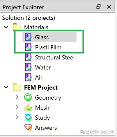
- Create a new FEM project.
- Add two material objects, named Glass and Plastic Film, respectively.

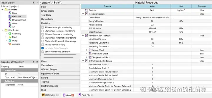
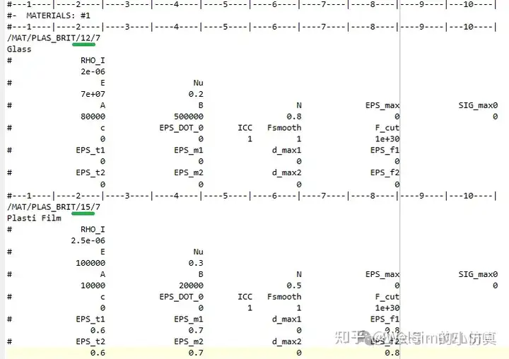
3. Double-click the Glass material object to enter the editing mode. Enter the initial density of 2.5e-6 kg/mm³, Young’s modulus of 70 GPa, Poisson’s ratio of 0.2, plastic yield stress of 80 MPa, hardening parameter of 500 MPa, and hardening exponent of 0.8. Add Orthotropic Brittle Failure properties with the default parameters set to 0.

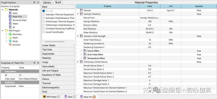
4. Double-click the Plastic Film material object to enter the editing mode. Enter the initial density of 2.5e-6 kg/mm³, Young’s modulus of 100 MPa, Poisson’s ratio of 0.2, plastic yield stress of 10 MPa, hardening parameter of 20 MPa, and hardening exponent of 0.5. Add orthotropic brittle failure properties with strain at the beginning of tensile failure set to 0.6, maximum tensile strain set to 0.7, and the maximum tensile strain for element deletion set to 0.8.

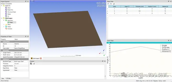
5. Add a plane shape to represent the shell structure. Users can also import a real shell structure. In the properties window, set the Structural Type to Multi-Layer Shell structure.

6. Once the Structural Type is set to Multi-Layer Shell, the table window is activated to edit layer data. This allows users to define the number of layers, angle, thickness, Z position, and materials for each layer. Here, a total of three layers are defined, with thicknesses of 1 mm, 0.5 mm, and 1 mm, and materials of Glass, Plastic Film, and Glass, respectively.

7. At this point, the multi-layer shell structure is defined and ready for subsequent analysis and computation. For example, an OpenRadioss input script can be generated to view the input layer data. As shown in the picture below, the material information and multi-layer shell structure properties are fully defined for solver.


Conclusion
This blog demonstrates the definition of a multi-layer shell structure and the associated material properties. This is the first step in composite material analysis. WELSIM makes it easy and quick to define multi-layer structures. This feature has been implemented in the 2025R2 development version and will continue to be optimized in future versions.
WelSim and the author is not directly associated with or the OpenRadioss development team or institutions. OpenRadioss is cited here only as a reference for the technical blog article and software usage.